electronics
What is a Voltage Divider / Potential Divider - How does it work? What are they used for?
A deep insight to demystify voltage dividers with plenty of demonstrations and uses. We cover everything you are going to need here, if you just need to learn for an exam, or if you want to understand how to use these incredibly useful voltage dividers in your projects.
- Overview
- Video Demonstrations
- The Basics
- Have A Play
- Voltage Divider Equation
- When Not To Use Voltage Dividers
- Useful Components When Used In A Voltage Divider
- Give Your Microcontroller Superpowers
- Potentiometers
- Potentiometers Uses
- Potentiometers To Attenuate A Signal
- Linear Or Logarithmic Potentiometers
- Conclusion
Overview
We got our hands dirty with potentiometers on our mini amp project and good a much deeper understanding of them.
This led to us using them in Pico Pong and our Pico Piano is pretty much a potential divider taken to the extreme. Once you get to know them they will be part of your toolkit forever.
We also learned about logarithmic & linear potentiometers and how to choose one for your specific project needs.
Video Demonstrations
The Basics
In a simple DC electrical series circuit the voltage or potential difference between each component when added together will equal the voltage or potential difference of the power source.

If we take 2 resistors connected in series the voltage from the power source is divided across each resistor. Hence voltage divider or potential divider. The way the voltage is divided depends on the ratio of the resistance of the 2 resistors.
In the simplest case when the 2 resistors are the same resistance the supply voltage is split evenly between the 2.
Have A Play
It's a good idea to do what we did and have a play around. Grab a battery, add 2 resistors in series and measure the voltage across each with a multimeter. It should add up to the voltage from your battery.
Try it with different resistors and see if you can get some kind of intuition on how the voltages are divided.
Voltage Divider Equation

You can figure out what voltage to expect using the equation above and rearrange to suit your needs. There are some worked examples in the video.
When Not To Use Voltage Dividers
You may be tempted to use this instead of a step down voltage regulator. It's inefficient and the circuit you want to drive will change the resistance. In the video we use a potential divider to get 3.65 volts then use that to drive a bluetooth module.
The voltage drops to 2.83 as soon as we add the bluetooth module demonstrating what a bad idea it is.
Useful Components When Used In A Voltage Divider
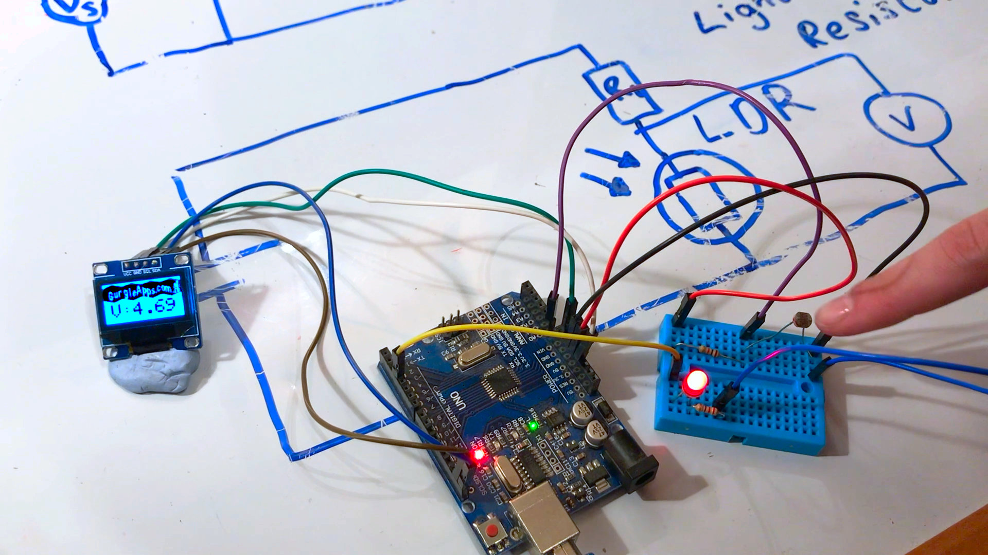
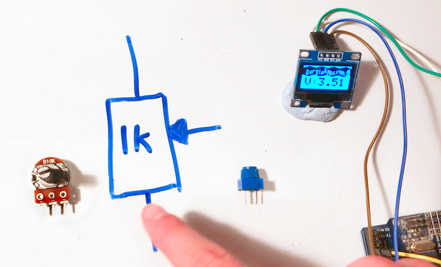
There are many component that change resistance due to changes in the environment. For example a light dependent resistor (LDR or photoresistor) changes resistance depending on the light it receives.
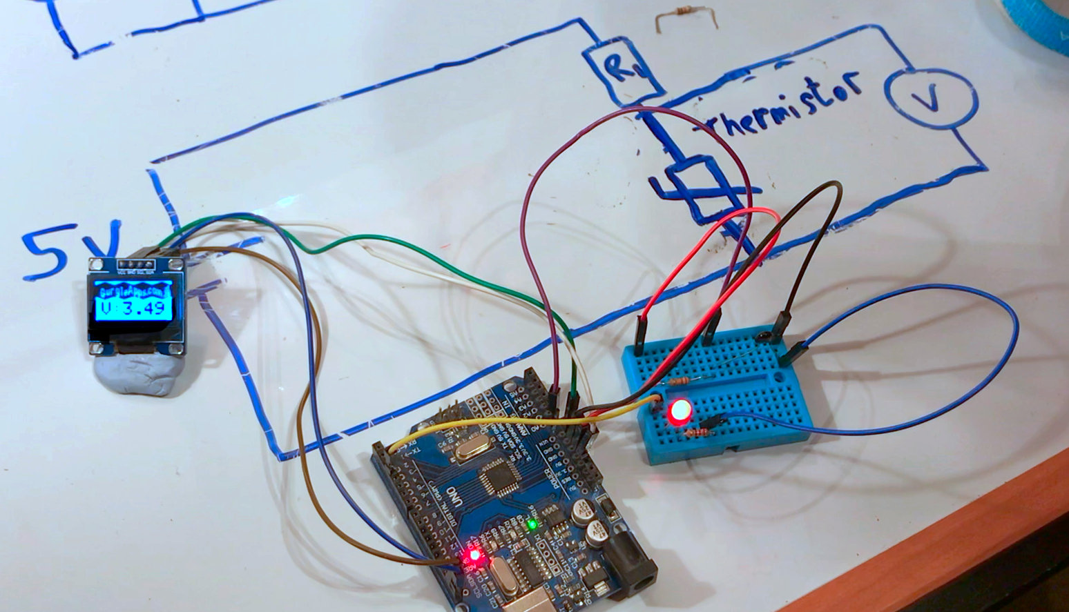
A thermistor changes resistance dependent on temperature, and you can find all sorts of other sensor components that change resistance depending on some physical change in the environment.
Give Your Microcontroller Superpowers
Microcontrollers such as Arduino, RP2040 boards, ESP8266 and the like can't detect changes in resistance. But many can detect changes in voltage, so using a simple voltage divider along with these cheap components such as LDRs you can make some amazing projects.
You will need to measure the resistance range of your sensor and choose a fixed resistor accordingly. You can use the formula and a bit of trial and error, in the video we had to change out the resistor for our Thermistor circuit.
You can also use a variable resistor (you can use a potentiometer as a variable resistor see later in tutorial) this way you can tweak your circuit by hand for various different environments.
Potentiometers
A Potentiometer has 3 legs and is essentially a voltage divider where you can adjust the ratio of the 2 resistors. The best way to understand how to use them is to compare it to the potential divider circuit we looked at earlier.
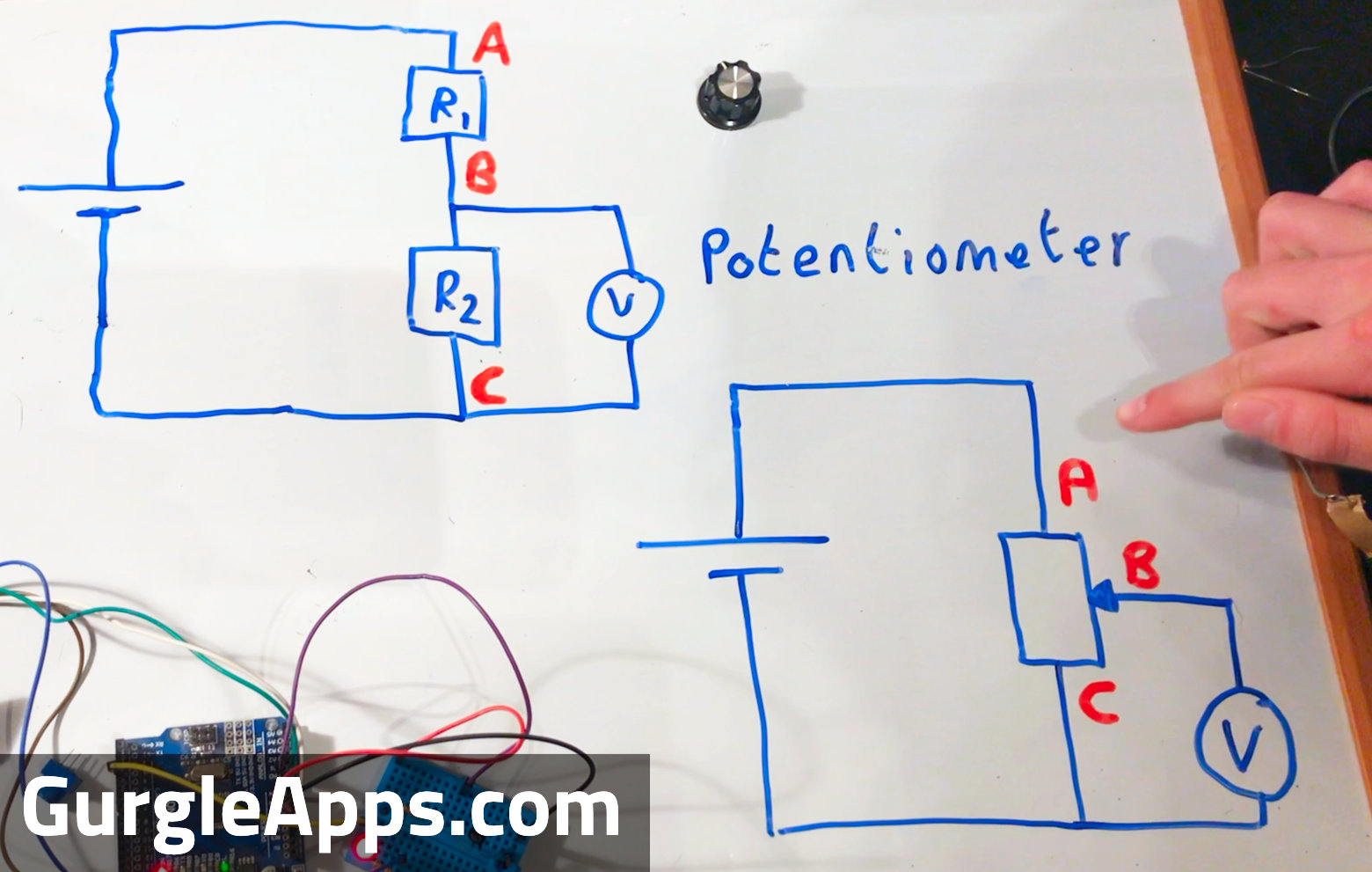
The 3 legs are A, B and C in the circuit. Resistor 1 is like A to B and resistor 2 is like B to C, as you turn your potentiometer resistor 1 gives some of it's resistance to resistor 2 and vice versa when you turn in the opposite direction. You can switch clockwise and anticlockwise/counter clockwise by switching the connections at A and C.
Potentiometers Uses
You could ignore one outside leg and use the potentiometer as a variable resistor and have nothing to do with voltage dividers. Or you could use it as a voltage divider, we used them in our Pico Pong project and they worked amazingly to move the paddle responsively.
Potentiometers To Attenuate A Signal
Until now our supply voltage has been fixed, but if the voltage was an audio signal for example then it would vary. In this setup our potentiometer acting as a voltage divider would still produce a varying voltage but it would be attenuated or reduced. As you turn your potentiometer it would adjust the attenuation or reduction of that signal acting like a volume control.
You will have seen potentiometers used in guitars and audio equipment to adjust volume and tone.
Linear Or Logarithmic Potentiometers
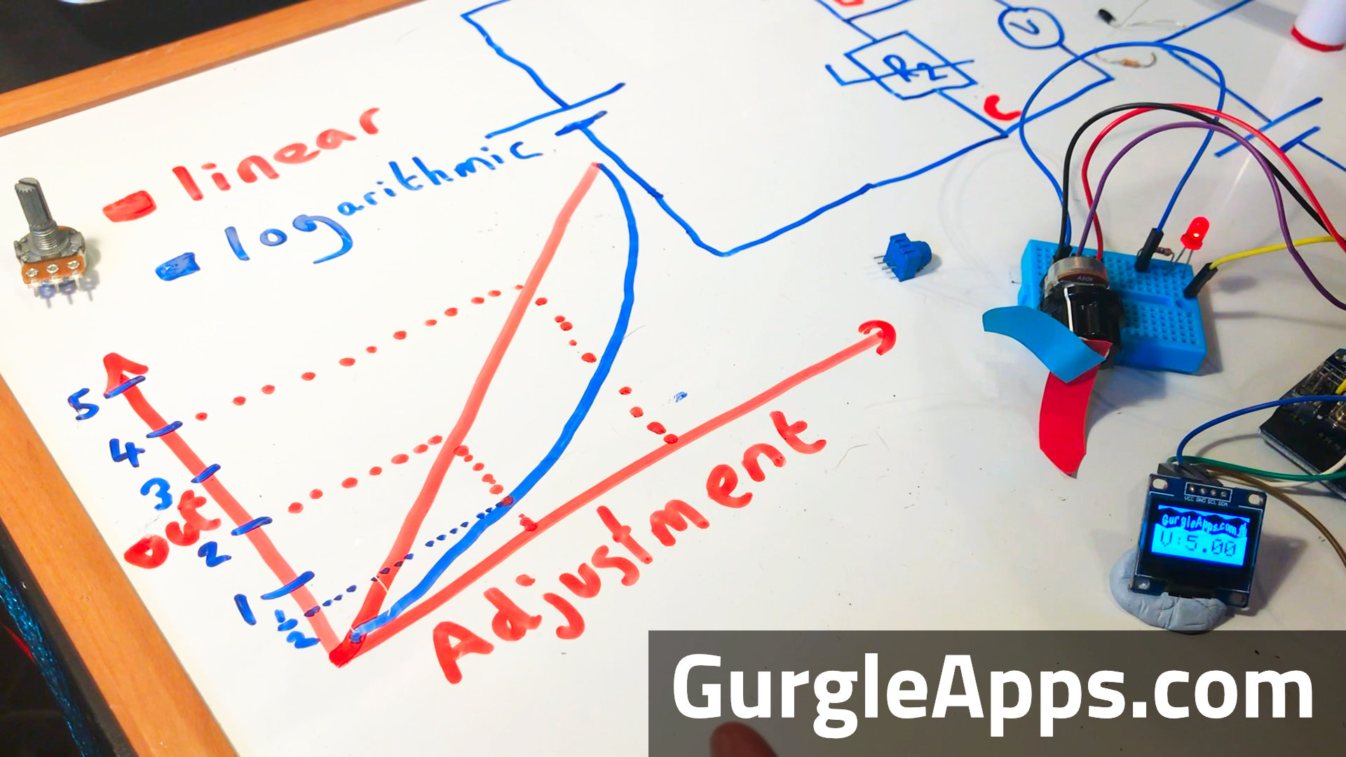
A linear potentiometer will do as you expect, the adjustment in resistance is proportional to how much you turn the dial.
A logarithmic potentiometer will start out adjusting in gradual smaller steps and increase the size of the steps as the dial is turned more and more. Why would you want to do this?
Well we sense light and sound logarithmically so adjusting a dimmer switch or volume control in a linear way would not seem linear to us. It may be worth playing with a dimmer switch using a linear and logarithmic potentiometer to convince yourself of this.
When we made our mini amp it felt like the volume control wasn't working until we used a logarithmic potentiometer.
Conclusion
Voltage Dividers and Potentiometers are extremely useful tools. The terminology and maths may be a little off putting but they are really simple to understand once to take the time to look into them. We've used them extensively in our projects since we fully understood those basic concepts. Hopefully they are now a part of your arsenal now, let us know how you put them to use.