projects
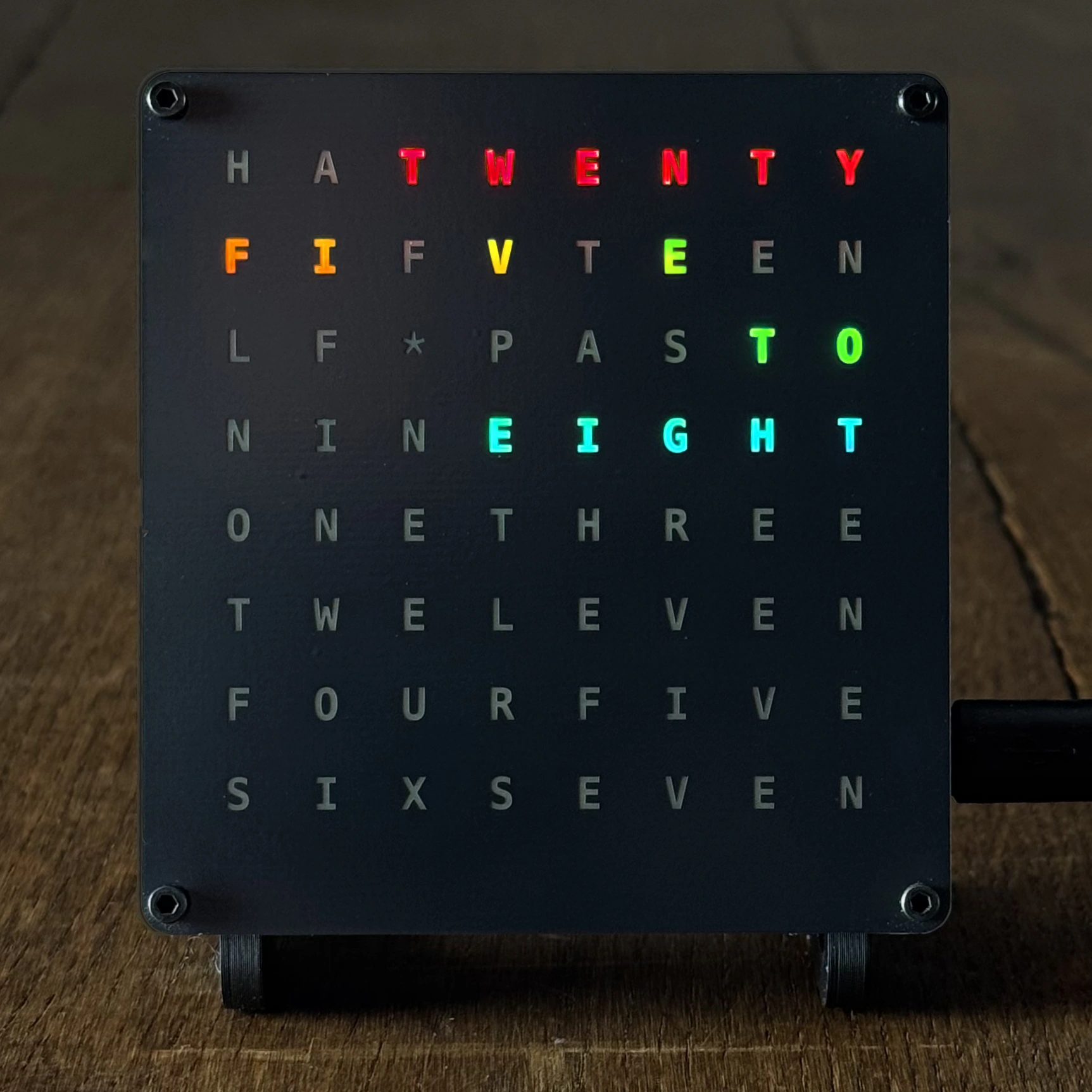
DIY WiFi-Controlled Word Clock Kit Assembly Guide
Welcome to our step-by-step guide on assembling your very own WiFi-controlled word clock. This unique DIY kit, featuring a 3D printed body, Raspberry Pi Pico W, and a colorful 8x8 matrix, is perfect for tech enthusiasts and makers.
Whether you choose to purchase our complete GurgleApps Color WordClock Kit, just the faceplate and LED matrix, or source your own parts, our guide and open-source code make it easy to bring your word clock to life.

- What's in the Kit
- Print Your Own Case Option
- Tools You’ll Need
- Assembly Instructions
- Full Video
- Step 1: Soldering the Components
- Step 2: Final Assembly
- Step 3: Setting Up the Raspberry Pi Pico W
- Software Setup & Configuring Your Wifi Word Clock
- Share Your Creation
- Customization Options
- Troubleshooting and Support
What's in the Kit
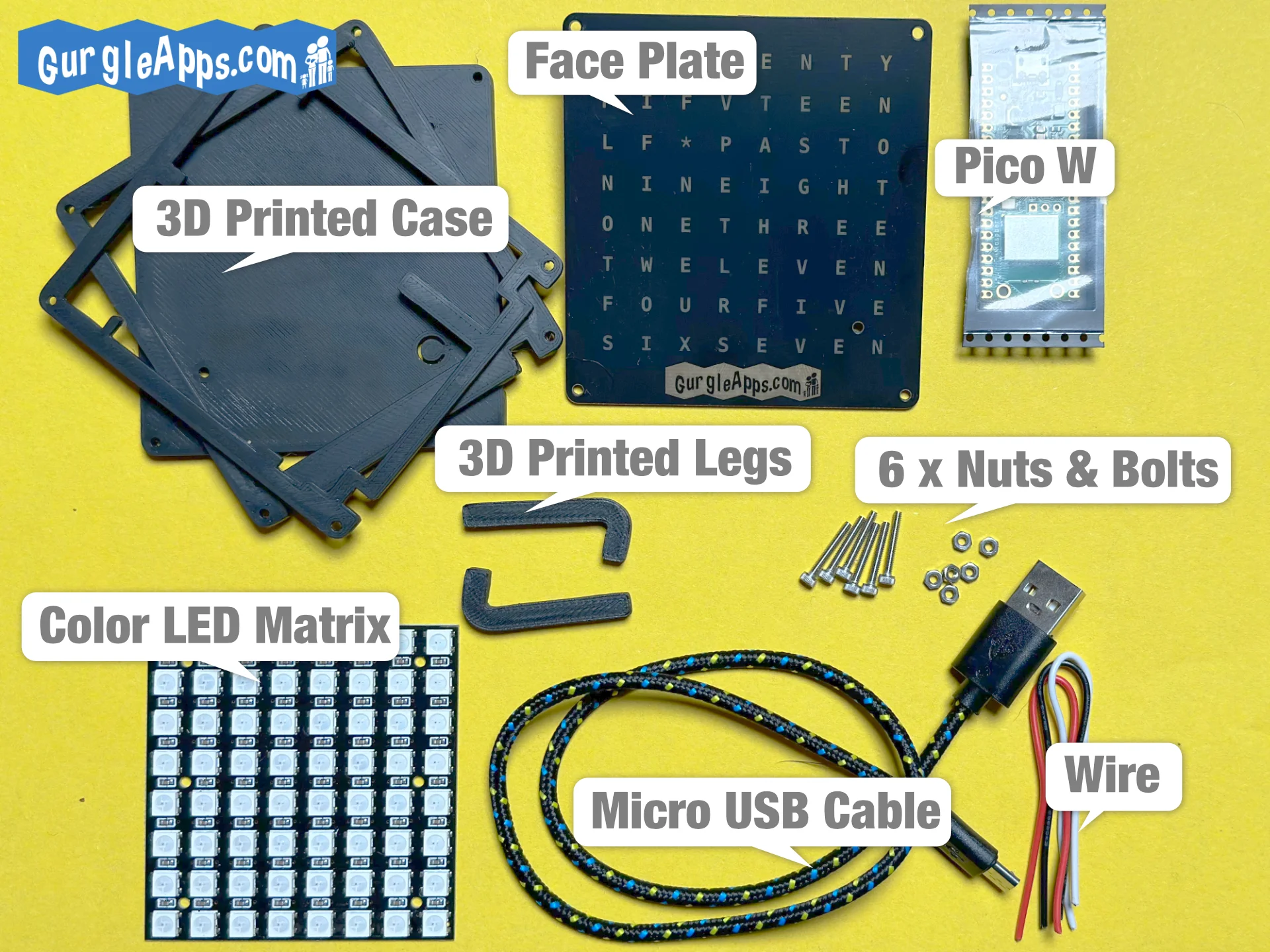
The full kit includes:
- High-Quality Face Plate
- 3D printed case and legs designed and printed at home by our fair hands
- Micro USB cable
- Raspberry Pi Pico W
- 6x bolts and nuts
Congratulations on unboxing your GurgleApps Color WordClock Kit! You're one step closer to bringing your unique timepiece to life.
Print Your Own Case Option
Everything is open source, if you didn't buy the case from us click here to get the 3D Printable Files or pick them up from our Word Clock GitHub Repo.
Tools You’ll Need
- Soldering iron & solder
- Glue Gun (optional)
Great job gathering all the necessary tools! You're well-prepared to start the assembly process.
Assembly Instructions
Follow these steps carefully to assemble your word clock. Remember to practice safety, especially when soldering: work in a well-ventilated area, wear protective glasses, and keep your workspace organized.
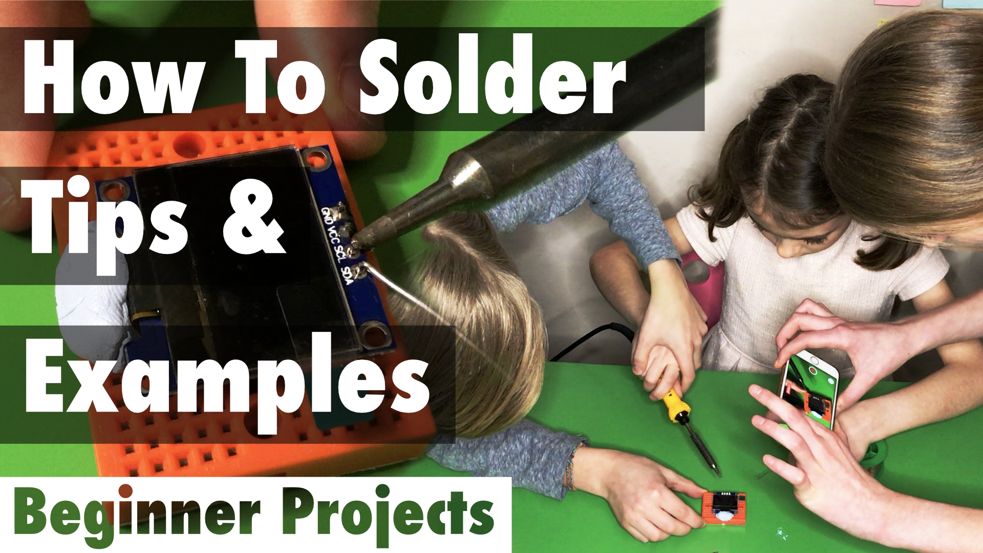
Full Video
Below is a full video of us assembling the word clock from our kit.
Note: If you bought an older version of the kit you will need to view our older assembly instructions.
Step 1: Soldering the Components
Properly soldering the components is crucial for the functionality of your word clock. Follow these steps:
-
Connecting the +ve Terminal (Red Wire):
- Identify the 3V3 out pin on the Raspberry Pi Pico W, which is pin 36.
- Route the red wire under the Pico and up through pin 36, ensuring a clean solder joint.
-
Connecting the Ground (Black Wire):
- Locate the ground pin, which is the 3rd pin from any edge on the Pico; we suggest using pin 3 for ease.
- Securely solder the black wire to this ground pin, ensuring it's well connected.
-
Connecting the Signal Wire:
- The remaining wire (usually white or yellow for clarity) connects to GPIO Pin 2 (4th pin) for the data signal.
- If you prefer using a different pin for data, remember to adjust the configuration in the software accordingly.
-
Attaching Wires to the LED Matrix:
- On the LED matrix, you'll find two solder areas labeled IN and OUT; connect the wires to the IN side.
- Solder the red wire to V+, the black wire to V-, and the remaining wire to the IN terminal.
- Ensure you leave enough slack in the wires for easy placement in the case without strain.
Remember to check each connection for solidity and to avoid any cold solder joints. A good solder joint is shiny and covers the wire and pad entirely without overflowing excessively.
Well done on completing the soldering! You've laid the foundation for your word clock's functionality.
Step 2: Final Assembly
Assembling the case and securing the components is straightforward if you follow these steps carefully:
-
Position the Faceplate: Place the faceplate face down, ensuring the GurgleApps logo is at the bottom. You'll be looking at a grid of 64 squares.
-
Install the LED Matrix: Lay the LED Matrix on top of the faceplate with the back facing you and the wires at the top right corner. Ensure the matrix aligns with the grid on the faceplate.
-
Prepare the Case: The case consists of three parts. Start with the frame that secures the matrix. This frame goes directly onto the faceplate, framing the matrix. Ensure the leg recesses are aligned at the bottom.
-
Secure the Matrix: Place the next part of the case on top. This layer traps the matrix in place and features four small raised areas for mounting the Pico. The leg recesses should again be at the bottom.
-
Mount the Raspberry Pi Pico W: Route the wires through the two frames and mount the Pico on the four raised pads. Optionally, use a hot glue gun for additional stability. Note: The raised pads are delicate; handle with care.
-
Assemble the Back: Attach the back of the case, holding everything together. Start by securing the assembly with two M2 bolts and nuts on opposite diagonals for stability. Then, use the remaining two to ensure everything is snug.
-
Install the Legs: Insert the legs into the recesses at the bottom of the case. Your clock should now stand on its own.
Note: The matrix alignment and Pico mounting are crucial steps. Take your time to ensure everything fits perfectly before securing it with bolts and nuts.
Excellent work assembling the components! Your word clock is now taking shape, thanks to your meticulous effort.
Step 3: Setting Up the Raspberry Pi Pico W
In the next step, we'll dive into configuring your Raspberry Pi Pico W, connecting it to your WiFi network, and uploading the word clock software. This is where your clock comes to life!
Congratulations on setting up your Raspberry Pi Pico W! You're just a few steps away from seeing your word clock in action.
Software Setup & Configuring Your Wifi Word Clock
Follow This Link for the Software Setup Guide
Share Your Creation
We love seeing our kits in the wild! Share your assembly process or your completed word clock on [Instagram/Twitter/Facebook] and tag us @GurgleApps. Join the GurgleApps maker community and see how others have brought their word clocks to life.
Customization Options
At GurgleApps, we understand the maker spirit is all about customization and flexibility. That's why we offer our WiFi-controlled word clock in various formats. You can buy the full kit from us, which includes everything you need to assemble the clock, or opt for just the faceplate and LED.
If budget is an issue you may wish to craft one from materials you already have.
-
Microcontroller Compatibility: While the kit includes a Raspberry Pi Pico W for its reliability, it's also compatible with other microcontrollers like the ESP32. We provide configuration files for alternatives, ensuring a broad compatibility range.
-
Case Flexibility: Use our provided .stl files to 3D print your case or get creative with materials like wood. The faceplate's mounting holes guarantee easy attachment to any project.
-
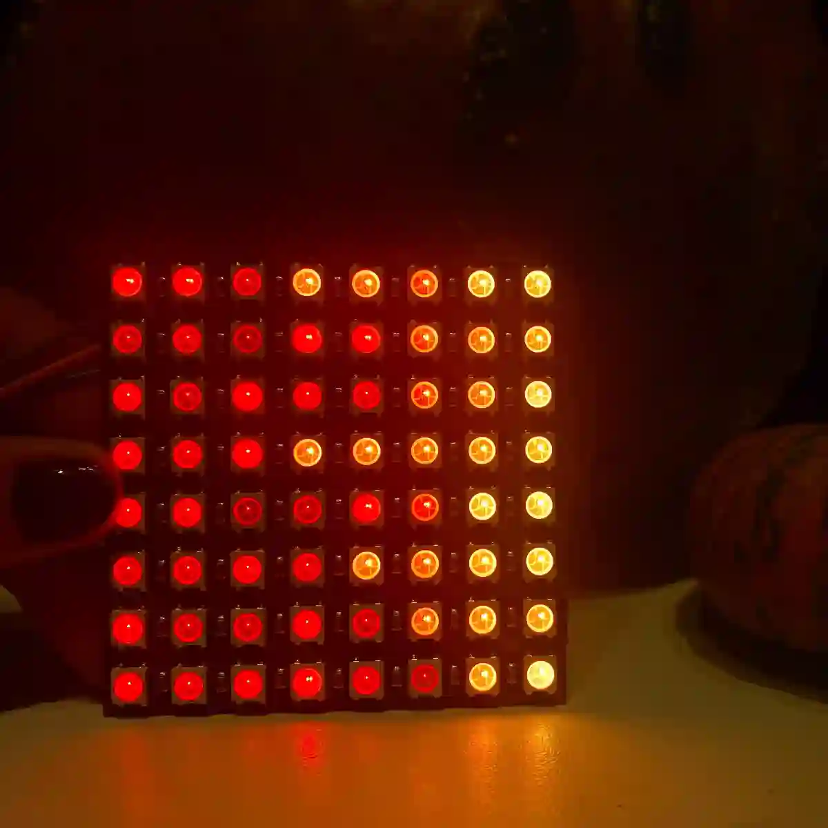
LED Matrix Options: Our kit's color matrix is a highlight, but you can also use other matrices like the 8x8 i2c ht16k33 or SPI max7219. Our matrix uses ws2812b LEDs which are cheap and easily sourced if you want to try making your own.
-
Faceplate Variations: Beyond the high-quality faceplate included, we offer .stl files for printing your own. This flexibility extends to users of smaller matrices, who can print templates on paper or transparency.
Troubleshooting and Support
Encountered an issue? Don't worry. This section will cover common troubleshooting tips to get your clock up and running.