projects
How To Build A Cheap Vibration Generator For Physics Experiments
In this DIY project, you will learn how to build an affordable and versatile vibration generator using a microcontroller and other readily available parts for a fraction of the cost of school equipment.
The generator can be used for a variety of applications, and the project is easy to complete, even for beginners. Plus, you can reuse the components for other projects.
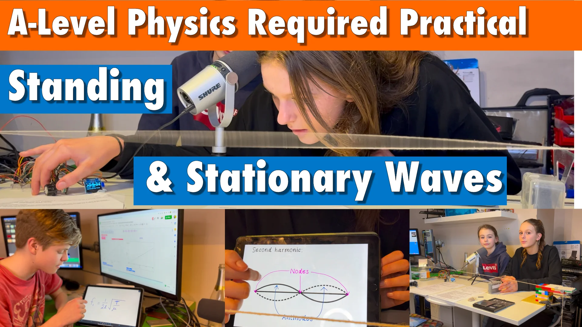
Check out our other resources to see the vibration generator in action and get ideas for its applications. We even use it to recreate a required A Level physics practical.
- Circuit Diagram
- Video
- Parts List
- Microcontroller
- OLED Screen
- Solenoid or Speaker
- Transistor and 9 Volt Battery / 9-12 Volt DC Supply
- Rotary Encoder
- Connecting Up
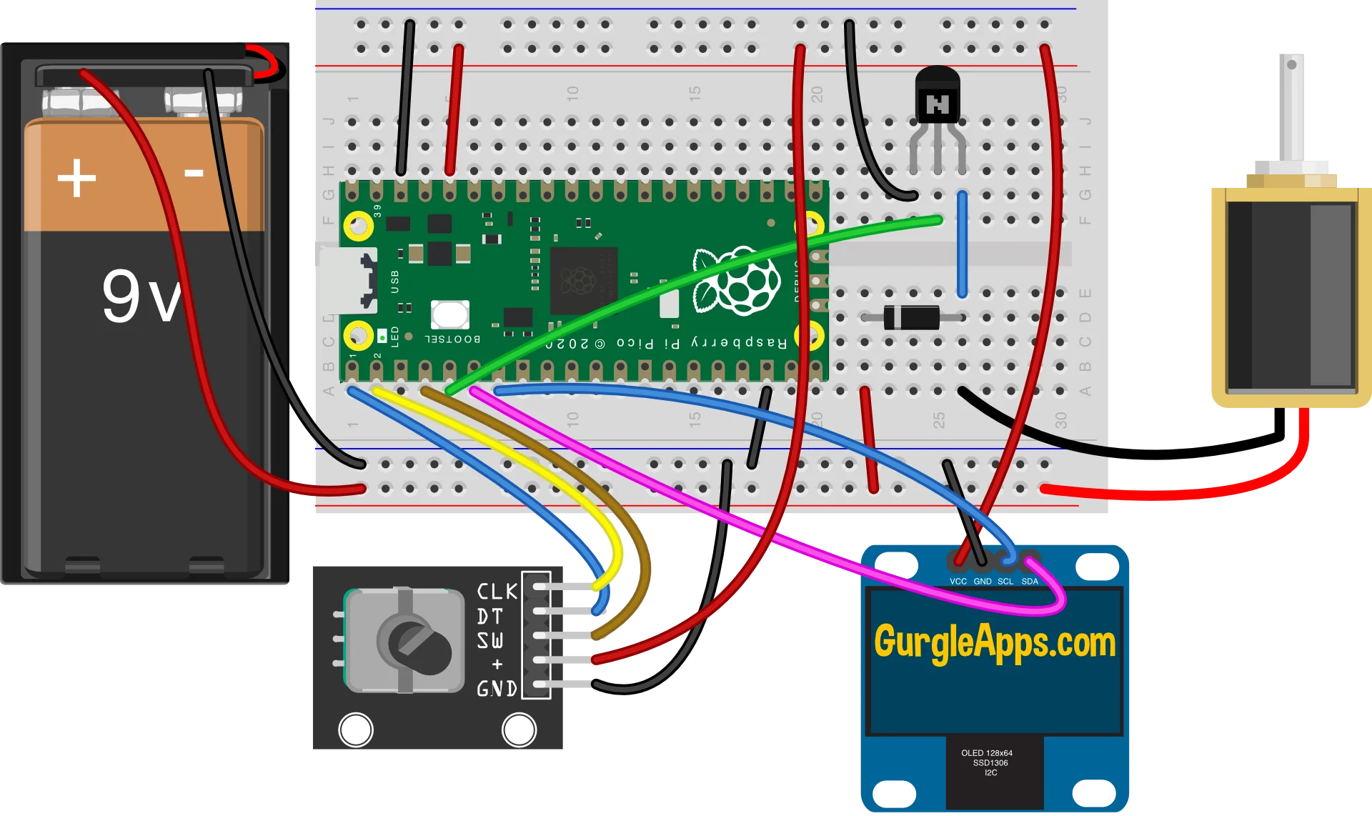
Circuit Diagram
As you can see, the circuit is very simple and only requires a handful of basic components, making it a breeze to put together.
Video
Parts List
To make your vibration generator, you will need the following materials:
- The code is available for free on GitHub.com
- Raspberry Pi Pico/RP2040 (or other microcontroller)
- USB lead or battery back to power the microcontroller
- Breadboard (optional but easier to prototype with)
- Jumper wires (or regular wire if not using a breadboard)
- Solenoid (a speaker could work too, but we used a 12V solenoid)
- OLED display SSD1306 (optional but useful to have a display)
- 9 Volt Cell and battery clip (or 9-12 volt dc supply)
- Rotary Encoder (optional could use a momentary switch)
- 2N2222 Transistor (there are alternatives 2N3904, BC547, BC548, and 2N3906 check the data sheets)
- 1N4001 Diode (for additional protection, will work without we used a 1N4002)
Microcontroller
There are many boards available that use the RP2040 chip.
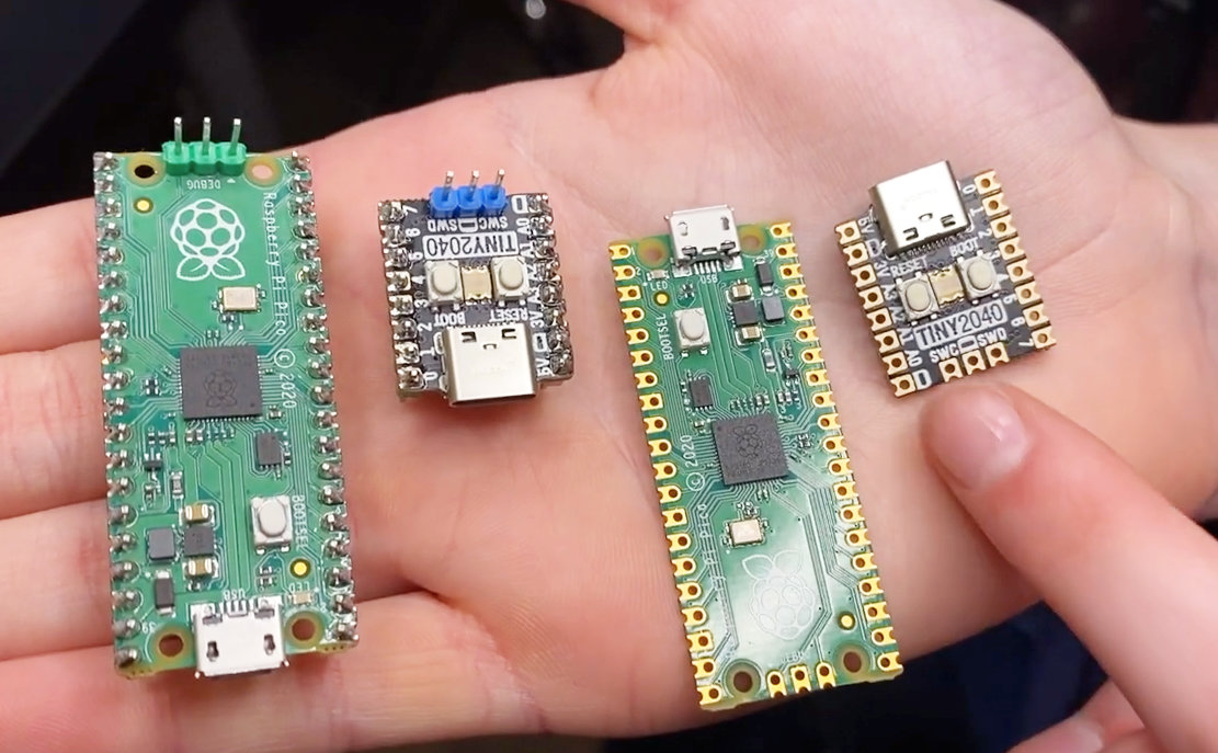
For this project, we used the RP2040 microcontroller, which is affordable and widely available. However, you can use almost any microcontroller for this project and may need to adjust the code slightly depending on your selection.
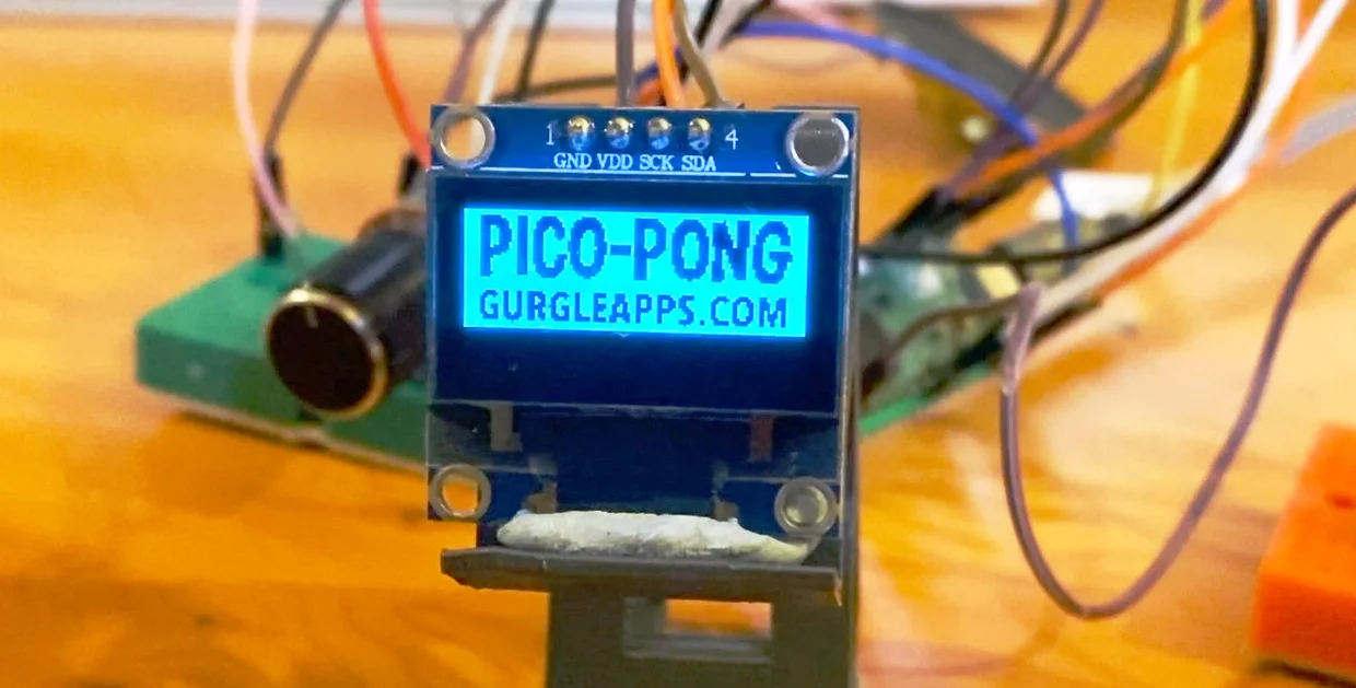
OLED Screen
An OLED screen is useful to display the frequency and on/off state. We selected an i2c SSD1306 display, which we bought for about £3.
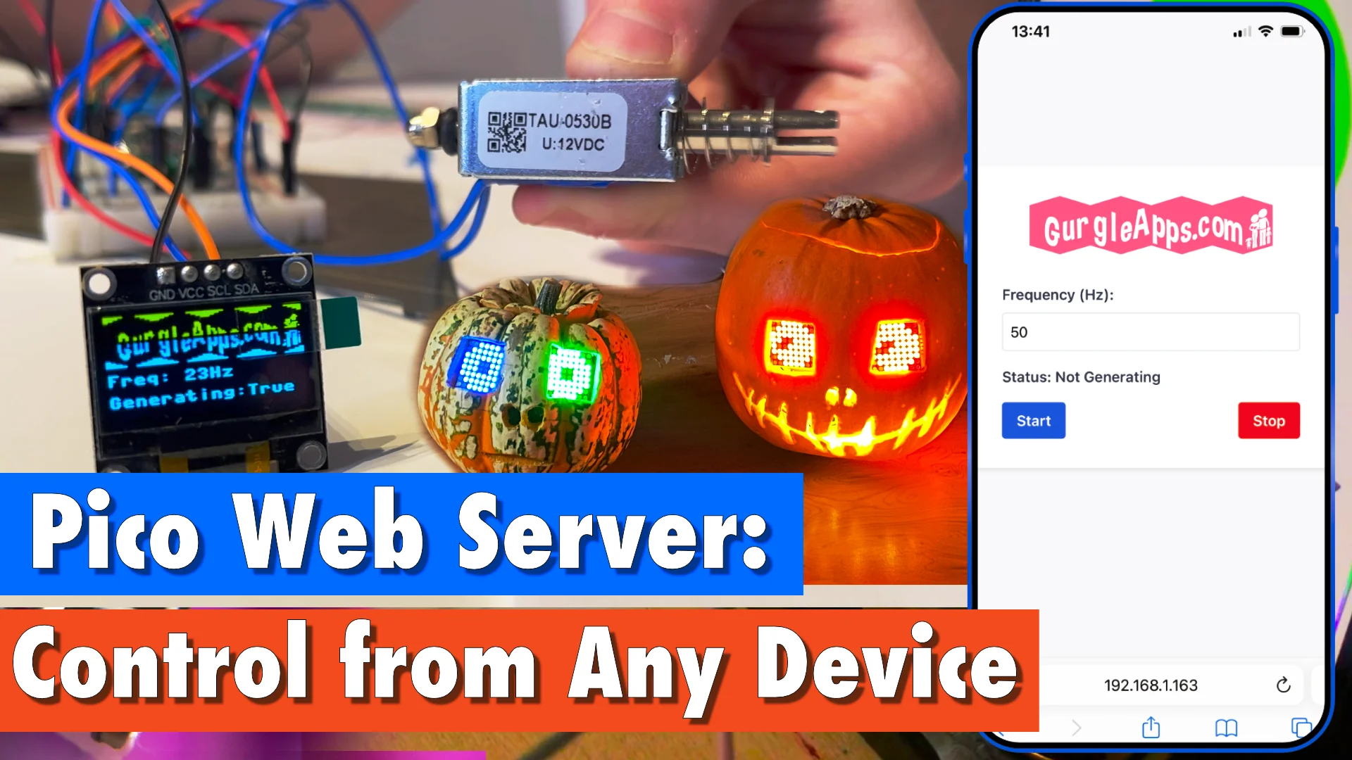
You could skip the screen and use Wifi or Bluetooth. Or run the code connected to a computer and have it print the frequency.

If you have a display you prefer then it would be easy to adjust the code to use your screen.
Solenoid or Speaker
We used a solenoid, but had good results with a speaker we took from a broken cabinet. We just glued a lego rod with a hole in it onto the speaker.
We made our own solenoid to get a deeper understanding of them, but they are so cheap to buy and will work better. We got a bunch for under £1 from AliExpress, some came in a week and another delivery turned up 6 weeks later.
Amazon delivered one the next day, it was 4 times the price but still 20 times cheaper than what we used at School.
We found some solenoids worked better than others we went for a 12 volt TAU-0520B and made another with an HS-0530B. A TAU-0520T was small but worked.
All of them worked but we were able to improve their performance.
Adding a small piece tubing on the underside of the shaft reduced the distance it moved an made the vibrations stronger.
Taking a spring out of a pen, straightening it out and making a small coil for a stronger spring also made an improvement.
Transistor and 9 Volt Battery / 9-12 Volt DC Supply
The voltage from the microcontroller isn't enough to give a strong enough vibration so we use a higher voltage from a 9-volt battery or DC supply.
The solenoid is connected to the higher voltage via a transistor and this is controlled by the microcontroller.
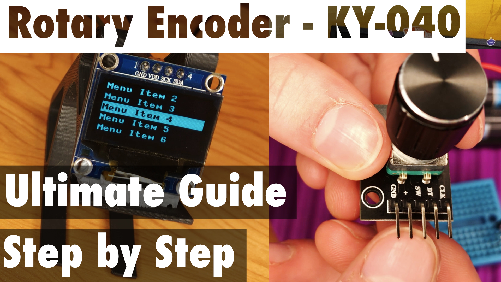
Rotary Encoder
You could use 3 cheap buttons instead or operate via wifi but a rotary encoder is cheap and practical.
A Rotary encoder allows us to have a dial to turn the frequency up and down. Many rotary encoders allow you to not just turn the dial but to push it to and operate a button. We used this button to turn the vibrations on and off.
We have an amazing article detailing how the rotary encoder works and a thorough coding tutorial or you can just copy our code and it will just work.
Connecting Up
We used breadboard and jumper wire which is probably the easiest way to get started. Breadboard and jumper wire is very cheap and easy to source.
-
First, insert the microcontroller into the breadboard. The ground pin is the 3rd pin from any end (pins 3, 18, 23, and 38). We recommend connecting the ground pin to both shared ground rails on the breadboard.
-
Connect the GND pin from the SSD1306 display, the GND pin from the rotary encoder, the negative terminal from the 9V battery or DC supply, and the emitter of the transistor to a breadboard ground rail. Check the datasheet of your transistor but our emitter was the leg on the left when the flat side was facing us.
-
Set up a high-voltage positive rail by connecting the positive terminal of the 9V cell or DC supply to a breadboard positive rail. We made our own 9 Volt Battery Clip from an old battery in this article or you can buy one for a few pence.
-
Set up a low-voltage rail pico positive (pin 36 of the pico) to the other breadboard positive rail.
-
Connect one of the terminals of the solenoid or the positive terminal of your speaker to the high-voltage positive rail.
-
Connect the positive terminal of the rotary encoder and SSD1306 OLED display to the low-voltage rail.
-
Complete the SSD1306 OLED display by connecting the SCL and SDA pins to the microcontroller. We recommend using I2C with pin 7 for SCL and pin 6 for SDA. You could use a different display or other pins if you prefer just tweak the code to match.
-
Connect the rotary encoder pins to the microcontroller. The DT and CLK pins of the encoder should be connected to pins 1 and 2, respectively. The SW (switch) pin should be connected to pin 4.
-
Connect the collector of the transistor to the other end of the solenoid or negative of your speaker, and the base of the transistor (which for us is the middle pin) to PWM (pin 5 of the microcontroller).
-
Finally, the diode is marked with a stripe at the cathode. This is connected in parallel with the solenoid to protect the transistor from spikes when the solenoid is turned off. The cathode to the positive of the solenoid and the other end to the negative of the solenoid.